Structures to control erosion in irrigation channel
- Severe erosion will occur in the earth channels, if structures to control the slopes are not produced.
- Drop structures and chute spillways are used to prevent erosion in field channels.
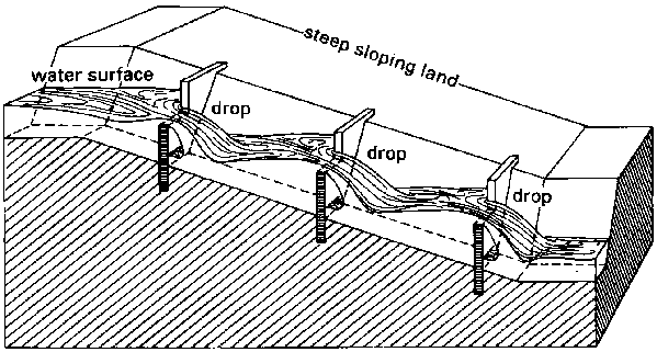
A. Drop Structures:
- Used to discharge water in channel from a higher level to lower one.
- These may be open type drops or pipe drops.
a) Open drops:
- It can be made of timber, concrete or brick or stone masonary.
- The check gate provided at the inlet of the structures is used to control the water surface heights on the upstream stretch of the channel.
- The minimum width of the inlet of the drop structure is equal to the bottom width of the irrigation channel.
- Water enters the structures through the inlet is in front of a weir or notch in a wall.
- Vertical wall known as “Cut off” wall, extends down into the soil under the inlet to prevent water seepage under the structures.
- Water falls into stilling basins which controls the erosive force of the water.
- The length of the stilling basin is twice the height of the drop.
- When the depth of over pour doesn’t exceed 30 cm, the water depth in the basin should be about 45 cm from drops upto 60 cm and 60 cm fro drops upto 60-90 cm.
- A small crosswall about 10-12 cm height is placed at the end of the basin which increases the energy of dissipation stones.
- This help to prevent channel erosion near erosion control structures.
b) Pipe drop structure:
- This type of structure allows the discharge of water through pipeline leaving the bund or dam undisturbed.
- A water tight lid at the inlet will function as check gate.
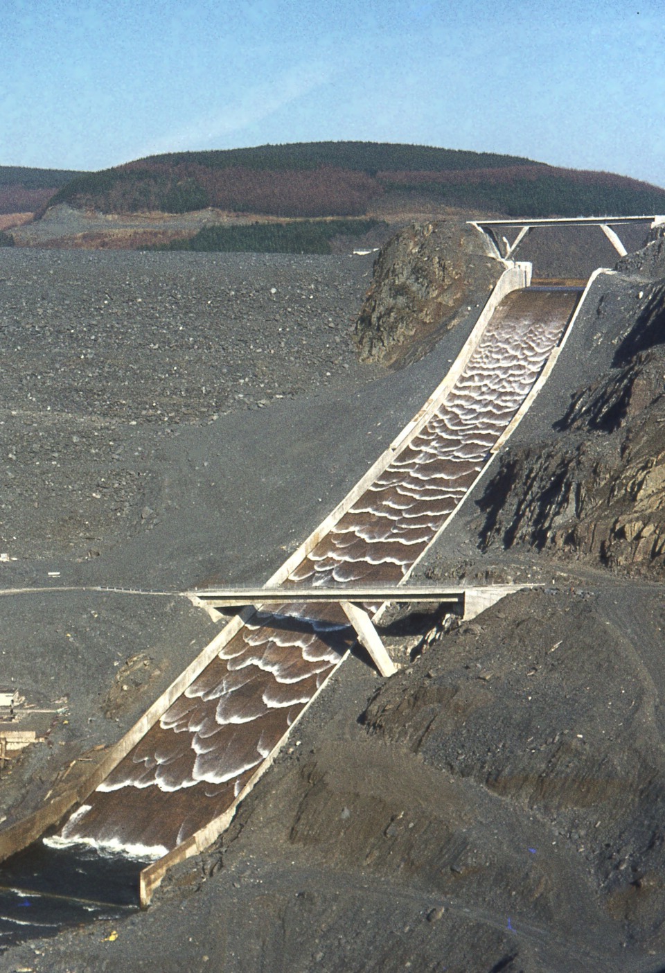
2. Chute Spillways:-
- It carry the flow down steep slopes through a lined channel rather than by dropping the water in a free overfall.
- The Chute Spillway consists of an inlet, channel section and outlet.
- It may be made of concrete or stone or bricks laid in cement mortar.
- It is constructed on steep slope usually rectangular in cross-section.
- Head drop is 5-6 cm.
- To minimize the problem of settling and undermining, the chuts are constructed on foundations on solid ground or on fill that has been carefully compacted.
- The velocity of flow of formula can be calculated as:
Available water = Friction loss in the pipe line + velocity head + Head loss at the entrance + Head loss at the bend
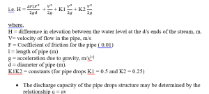
Where,
q = discharge , m3/sec.
a = area of cross section of pipe, m2
v = velocity of flow , m/sec.
- When the high velocity is slowed down to a low velocity in a stilling basin, there is a sudden rise in the depth of flow which is known as “hydraulic jump”.